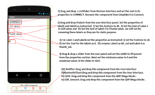
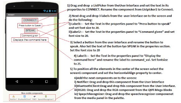
Introduction to Robotics
A robot is a machine that does tasks without the help of a person. Many people think of robots as machines that look and act like people. Most robots, though, do not look like people. And robots do only what a person has built them to do.
Robotics develops machines that can substitute for humans and replicate human actions. Robots can be used in many situations and for many purposes, but today many are used in dangerous environments (including inspection of radioactive materials, bomb detection and deactivation), manufacturing processes, or where humans cannot survive (e.g. in space, underwater, in high heat, and clean up and containment of hazardous materials and radiation).
| Component | Description |
|---|---|
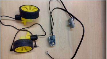
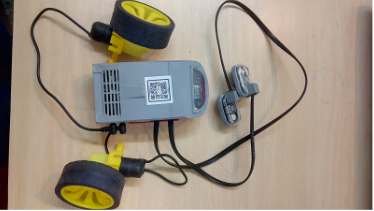
| QBrick |
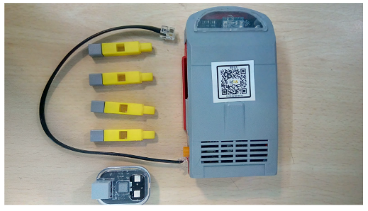
• Qbrick or motherboard is the brain of the robot. • It is powered by a rechargeable battery and switched ON manually. • It has 6 programmable RJ ports for sensors and actuators. • Also includes 2 programmable & 1 non-programmable motor ports. |
| QBit |
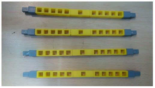
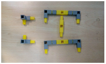
• Qbits are the building blocks used to build a structure for the robot. There are 6 types of building blocks: – 5 Hole pillar, Connector, T block, L block – Angle block (45°), I block, Wheels, Castor, Belt & Shaft |
| RJ Cables |
• RJ stands for Registered Jack, a telecom interface standard. • Used for connecting voice/data equipment to service networks. • RJ cables ensure smooth data processing and connectivity. • The RJ11 is the most widely used in telecom systems. |
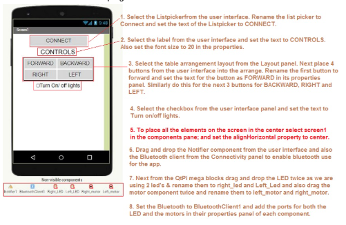
General Coding Components used:
| Component | Description |
|---|---|
| List Picker |
• ListPicker is a button that displays a list of items. • It shows available Bluetooth devices for selection. • You can change its text, color, height, and width. • All customization is done via the properties panel. |
| Label |
• Used to display static or informational text. • Labels are non-clickable and fixed on screen. • Commonly used for titles, instructions, etc. • Can be styled for font size and alignment. |
| Buttons |
• Buttons trigger actions when the user taps them. • You can modify their color, text, and shape. • Use the Enabled property to activate/deactivate. • Essential for interaction in your app interface. |
| Notifier |
• A non-visible component to show alerts or logs. • Helps notify users with messages or warnings. • Useful for debugging and user instructions. • Can display info, errors, and confirmations. |
| Bluetooth Client |
• Provides Bluetooth communication features. • Used to connect with external Bluetooth devices. • Handles data transfer between app and device. • Essential for robot control or IoT applications. |
Testing the app.
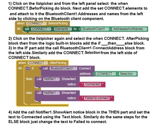
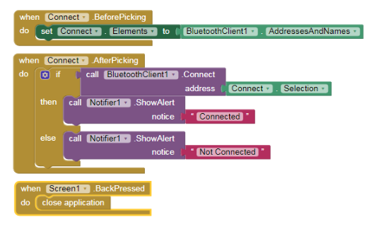
Start the bluetooth for the device and pair it with the qbrick( the qbrick number will be shown in the available devices).
First go the Build item of the menu bar and click on the App(provide QR code for apk).
Scan the Qr code with the MIT AI2 Companion app and download and install the app.
After installing the app, open it and click on the Connect button, it will take you to another black screen which will show the Qbrick version number, click on that and wait for a few seconds till your app is connected.
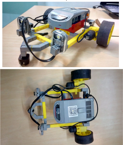
Project 1: Lyanna’s RC car with headlights
Robot Components Index:
| Component | Description |
|---|---|
| LED |
• LED stands for Light Emitting Diode with two terminals. • Anode (Positive) – Longer; Cathode (Negative) – Shorter. • It emits light when electric current passes through it. • Used in indicators, displays, flashlights, and sensors. |
| DC Motors |
• Converts electrical energy into rotary motion. • Based on the principle of magnetic field force. • Speed range: 0 to 255; rotates both directions. • Used in pumps, fans, wheels, and compressors. |
Coding Components Index:
| Component | Description |
|---|---|
| LED |
• Used to program the hardware LED component. • Allows control over when the LED turns on or off. • Helps in signaling or status indication in robots. • Controlled via software logic in your program. |
| Motor |
• Used to program the hardware motor component. • Set wheel rotation speed and direction easily. • Controls movement actions of the robot precisely. • Ideal for navigation and task execution routines. |
Assemble the project
Tasks Division:(Similar for making and breaking the model) Divide the below tasks to each 4-kids group
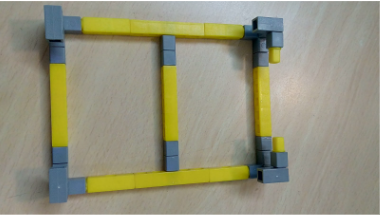
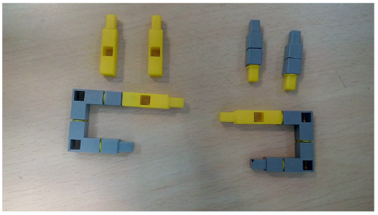
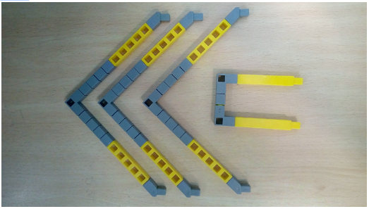
Task 1: Create the base of the RC(Remote Control) car using Qbits.
Task 2: Create the support columns for the QBrick and the block for attaching the castor wheel to the RC(Remote Control) car using Qbits.
Task 3: Connect the wheels to the DC motor and also attach one end of the RJ cables to the LED.
Task 3: Connect the wheels to the DC motor and also attach one end of the RJ cables to the LED.
Steps to make the model:
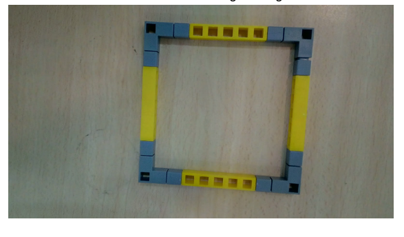
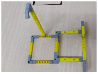
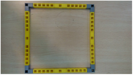
1.First take the base of the RC car as shown in Task
- 2.Next attach the support columns at the back side corners of the base and also fix the frame for attaching the castor wheel. Your model should look like the below picture.
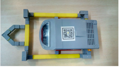
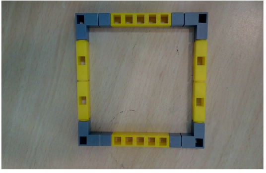
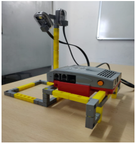
3.Next attach the QBrick to the RC car using the support beams at the back.
Also attach the frame for the castor wheel created in task 2.It should look like this.
4.Now connect the 2 LED’s to the front of the car and the wheels at the back on either side of the car.
5.Add the LED cables on appropriate ports as well as the wheels as we will be using it for our code.
6.Your final model will look like the below picture.
Task division:
4 students will share the same computer. Each student will code at least one set of code block.
Coding the Model
1. Follow the steps given below.
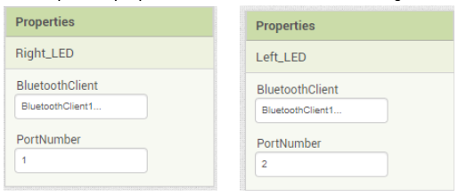
2. Do the following changes for the Right_LED and Left_LED component properties as shown in the below images:
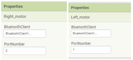
3. Do the following changes for the Right_motor and Left_motor component properties as shown in the below images:
4. Now go to the Blocks panel to code the app.
5. Perform the below steps in order.
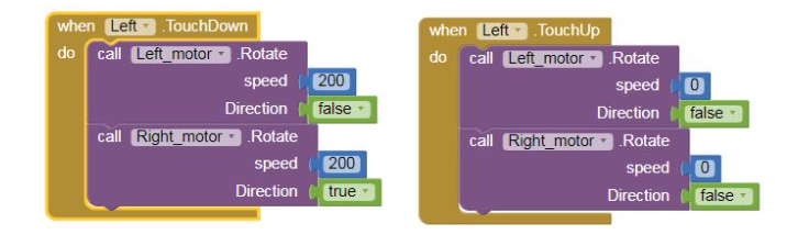
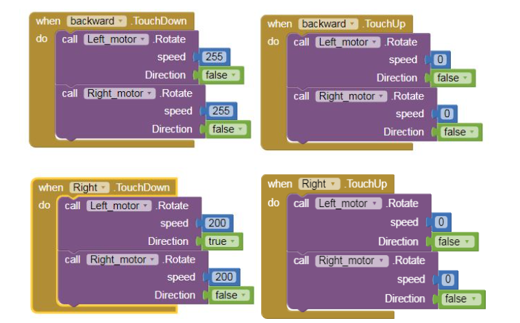
6) Now select the forward button and from the left panel select the when forward .Touchdown do block. Next add the call Left_motor .rotate speed direction block & call right_motor .rotate speed direction by choosing the Left motor component and the right_motor component respectively set the speed and direction.
7)Also add the when forward .Touchup do block and add the call Left_motor .rotate speed direction block & call right_motor .rotate speed direction by choosing the Left motor component and the right_motor component respectively set the speed and direction. Refer to the below picture.
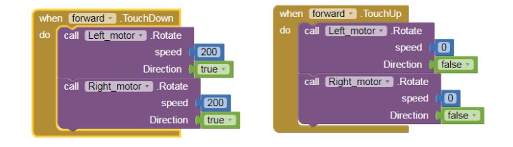
8) Repeat step 6 and step 7 for coding the backward, left and right buttons.
Refer the below images.
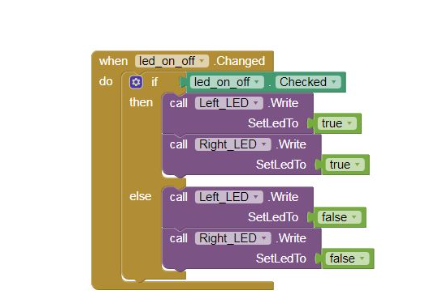
9) Select the checkbox and next choose the when led_on_off. Changed do block from the left panel. Add the if ___ then__else block from the control built in blocks.
10)In the if part add the led_on_off.checked block. The condition will be true if the checkbox is checked and the then part will execute, if checkbox unchecked then false and the else part of the If____then___else block will execute.
11)In the then part add the call right_led.write set Led to block from the left panel by clicking the right_led component and from the logic blocks add the true block.Do the same for the left_led component.
12) In the else part again repeat the call _____.writesetledto block. Your code should be as given below.
Tips to Code
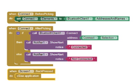
Note: Steps 2 , 3 and 4 are for connecting the app to the model via bluetooth and hence are common in every project. Do avoid doing it again and again for all projects do the following steps:
- i) In the right corner of the Blocks screen there is a bag, select the complete block and drag and drop it into the bag.
- ii) Click on the bag and should see all the blocks of steps 2,3 and 4 in the bag. To use the blocks in the next project simply drag and drop the blocks from the bag
Project 2: Aaron’s Automatic Street Lights
| Component | Description |
|---|---|
| LED (Light Emitting Diode) |
• LED stands for Light Emitting Diode. It has two terminals: – Anode (Positive): Longer terminal – Cathode (Negative): Shorter terminal • Emits light when electric current flows through it. • Used in indicator lights, signs, clocks, and flashlights. • Can emit infrared light for sensors (e.g., TV remote). |
| LDR (Light Dependent Resistor) |
• A light-controlled variable resistor. • Resistance decreases in light. • Resistance increases in the dark. • In darkness, resistance is high – called dark resistance. |
| Component | Description |
|---|---|
| LED |
Used to program the hardware LED component. You can control when the LED turns on or off through the app. |
| LDR |
Represents the hardware LDR Sensor in the app. This block connects to the robot model via Bluetooth. The data sensed by the LDR is accessed using various methods provided in the app block. |
Assemble the project
Tasks Division:(Similar for making and breaking the model)
Divide the below tasks to each 4-kids group
Task 1: Create the base of the street light using Qbits.
Task 2: Create the base for the support for placing the QBrick on.
Task 3: Create 4 columns for the support table for Qbrick and also the frame that will keep the Qbrick stable.
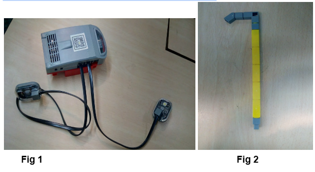
Task 4: Create the streetlight pole which will be connected to the base. Also connect the LED to port 2 and LDR sensor to port 1
Steps to make the model:
1.Take the base for the streetlight (as made in Task 1) and attach the pole of the street light(refer Task 4—>Fig 2) to the base.
2.Connect the base for the support table you created (refer Task 2) to the base of the streetlight using the columns made in Task 3. Also add the frame for attaching the QBrick.
3.Your model now should resemble the below given picture.
4. Next connect the Led to the 45 degree block and the LDR sensor to the L Block.The completed model will look like the below image.
Task division:
4 students will share the same computer. Each student will code at least one set of code block.
Coding the Model
1.Follow the steps given below.
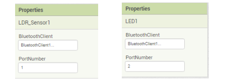
2.Do the following changes for the LED and LDR sensor component properties as shown in the below images:
3.Now go to the Block panel of the screen and let’s write some script.
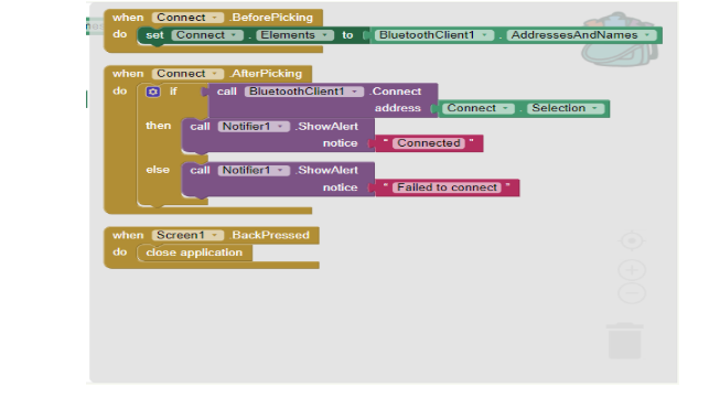
The bluetooth Connectivity part of blocks is the same as project 1.
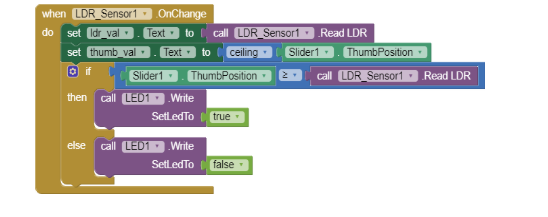
4.Next click on the LDR_sensor1 on the left side panel and select the when LDR_Sensor1. OnChange do block.
5.Now we have to set the text for the ldr_val label so choose that component and select the set ldr_val . text to block. Next select the call LDR_Sensor1. ReadLDR block from the left panel.
6.Similarly set the text for the thumb_val by then going to the Math built in block and select the ceiling block. Next select the slider1 component and from the blocks panel select the Slider1.ThumbPosition block.
7.Go to the control panel and select the If ____ then____ else block.In the IF part select the comparator block from the Math blocks and set the first operand as Slider.ThumbPosition and the second operand as call LDR_sensor1. ReadLDR.
8.In the Then part add the call LED1. WriteSetLedTo block by clicking on the Led1 component and set the value to true using the logic block.
9.Copy the step 8 for the else part of the IF_____ then___else block but set the value to false.Your code should resemble the below picture.
Project 3: Dia’s Automatic DoorBell
| Component | Description |
|---|---|
| Buzzer | • A buzzing audio signal device. • Operates on the principle of applying an electric potential to a piezoelectric material, creating pressure variations. • These pressure variations generate audible sound waves. |
| IR Sensor (Infrared Sensor) | • Infrared Radiation (IR) is a type of Electromagnetic Radiation (EMR) with longer wavelengths than visible light. • It is typically invisible to the human eye. • An IR sensor is used to detect or emit IR radiation to sense environmental characteristics. • Contains a Transmitter (TX) to emit IR rays and a Receiver (RX) to detect the reflected rays when an object is detected. |
| Component | Description |
|---|---|
| Buzzer |
Used to program the hardware buzzer component. You can control when and how the buzzer activates through coding blocks in the app. |
| IR Sensor |
Represents the hardware Infrared Sensor in the app. This block connects to the robot model via Bluetooth. The sensor data is accessed through the app using various block functions. |
Assemble the project
Tasks Division:(Similar for making and breaking the model)
Divide the below tasks to each 4-kids group
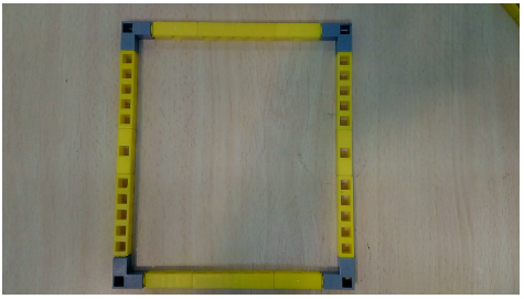
Task 1: Create the base of the house using Qbits.
Task 2: Create the half triangle to make the roof of the house and the door using Qbits.
Task 3: Create the base of the roof of the house using Qbits.
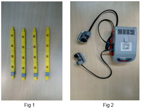
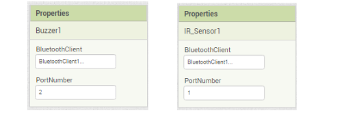
Task 4: Create 4 pillars to connect the base and roof of the house using Qbits. Also connect the IR sensor to port P1 and Buzzer to port P2 on the Qbrick.
Steps to make the model:
1.Take the base of the house as made in task 1.
2.Attach the 4 pillars(Refer task 4 —> Fig 1) on the 4 corners of the base.
3.Next attach the roof base made in task 3 to the 4 pillars.You will have a cube like structure now.
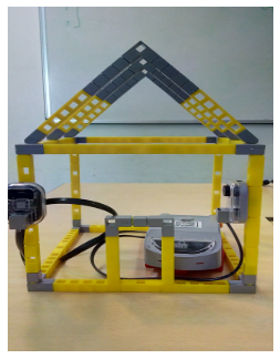
4.Attach the 3 half triangles to the top of the roof base and connect the door at one side of the cube.Your model now should look like the below picture.
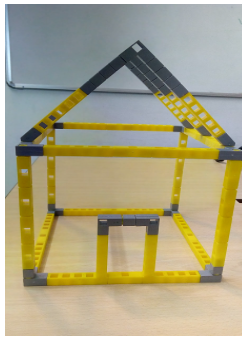
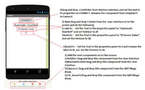
5.Next connect the Buzzer facing inwards to the door and also the IR sensor facing outwards. Connect the Buzzer and IR Sensor to the ports on the Qbrick and your complete model will look like the below image.
Task division:
4 students will share the same computer. Each student will code at least one set of code block.
Coding the Model
1.Follow the steps given below.
2.Do the following changes for the LED and LDR sensor component properties as shown in the below images:
3.Now go to the Block panel of the screen and let’s write some script.
The bluetooth Connectivity part of blocks is the same as project 1.
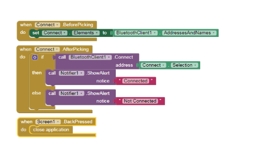
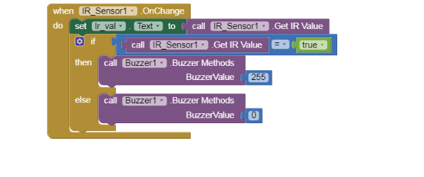
4.Next click on the IR_sensor1 on the left side panel and select the when IR_Sensor1. OnChange do block.
5.Now we have to set the text for the lr_val label so choose that component and select the set lr_val . text to block. Next select the call IR_Sensor1. Get IR value block from the left panel.
6.Go to the control panel and select the If ____ then____ else block.In the IF part select the comparator block from the Math blocks and set the first operand as call IR_Sensor1. Get IR value and the second operand as the true block from the logic built in blocks.
7.In the Then part add the call Buzzer1. BuzzerMethods BuzzerValue block by clicking on the Buzzer1 component and set the value to 255 using the math block.
8.Copy the step 8 for the else part of the if_____ then___else block but set the value to 0.Your code should resemble the below picture.
Project 4: Caroline’s Voice Controlled RGB
| Component | Description |
|---|---|
| RGB LED |
• RGB stands for Red, Green, and Blue — the primary colors of light. • By mixing these three colors, a wide range of other colors can be created. • RGB LEDs are widely used in screens, city decorations, home lighting, LED matrices, and even LCD/projector backlighting. • It functions as an actuator, with each color channel ranging from 0 to 255 to control intensity and produce different colors. |
Coding Components Index:
| Component | Description |
|---|---|
| RGB |
Used to program the hardware RGB LED component. You can set values for Red, Green, and Blue light from 0 to 255. For example, set Red = 255 to light up red, Green = 255 for green, and so on, or combine values to mix colors. |
Assemble the project
Tasks Division:(Similar for making and breaking the model)
Divide the below tasks to each 4-kids group
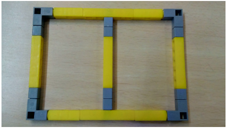
Task 1: Create the base of the table using Qbits.
Task 2: Create the railings to fill between the frame of the table using Qbits.
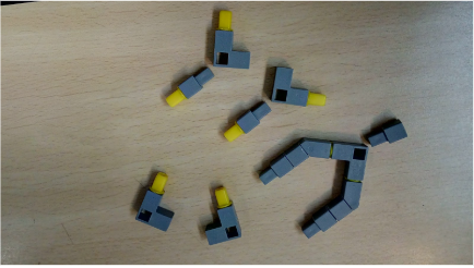
Task 3: Create the small H shape structure to connect the RGB Led as well as the frame for connecting the Qbrick to the table using Qbits.
Task 4: Create the legs of the table using Qbits. Also connect the RGB to port P1 of the Qbrick.
Steps to assemble the model:
1.Take the base of the table as made in task 1.
2.Add the railings(made in task 2) in the middle of the base as shown below.
3.Next attach the support to connect the QBrick to the Table and also connect the H- base structure on top of the table using railings. Also add the legs of the table made in task 4.
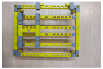
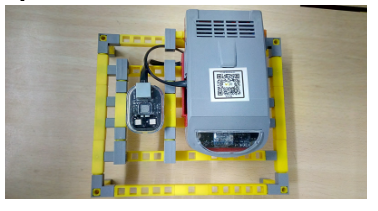
4.Next add the RGB on top of the H-base structure and attach the Qbrick to the table using the supports.Connect RGB to the Qbrick.Your complete model should be like the below image.
Task division:
4 students will share the same computer. Each student will code at least one set of code block.
Coding the Model
1.Follow the steps given below.
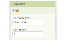
2.Do the following changes for the RGB led component properties as shown in the below images:
3.Now go to the Block panel of the screen and let’s write some script.
The bluetooth Connectivity part of blocks is the same as project 1
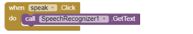
4.Select the speak button and choose when speak .Click do block from the left panel.
5.Next select the SpeechRecognizer component and choose the call SpeechRecognizer. GetText block.
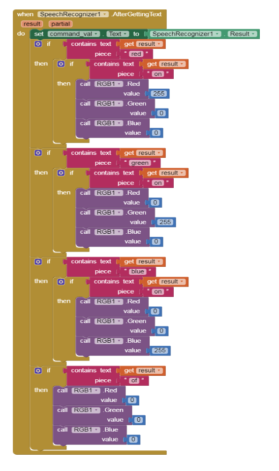
6.Select the SpeechRecognizer1 component and choose the when SpeechRecognizer1.AfterGettingText do block from the left panel.
7.Next set the text for the command_val label SpeechRecognizer1.result block.
8.Add the If __ Then block from the Control built in blocks. In the If part from the text built in block add the contains Text ___ piece block. Select the get result block from the result block inside the when SpeechRecognizer1.AfterGettingText do block and select text block and set its value to red.
9.In the Then part of the If___ then block add another If ___then block. For the If part of this block repeat step 6 just change the text from “red” to “on”. In the then__ part of this block add the call RGB1 . RedValue block and set it to 255,add call RGB1 . GreenValue & set it to 0 and finally the call RGB1 . BlueValue and set it to 0.
10.Repeat step 6 and step 7 to code for the Green colour and the Blue colour.
11.Repeat only step 7 to write the code for switching the RGB.
12.Your code for steps 4 to 9 should look like the below given image.