Introduction to Robotics
Our daily lives are already surrounded by robots.What? Sounds unreal? So how do you define the process that makes the washing machine go round and round? how does the modern age vacuum cleaner change direction when it’s about to hit a wall?
The applications of Robots are growing more than ever and robots are helping us in each and every industry. At present, robots are performing medical operations, working as hotel staff, can defuse bombs, do household chores, entertain us as games and do many more tasks.
Skills you gain in robotics:
1.Programming
2.Designing thinking
3.Product development
4.Analytical skills
5.Logic building
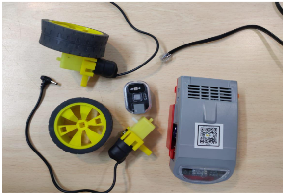
General Model Components Used:
| Component | Description |
|---|---|
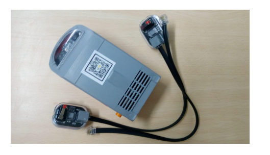
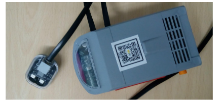
| QBrick |
• Acts as the robot’s motherboard or brain unit. • Powered by a rechargeable battery and turned ON via a switch. • Includes 6 programmable RJ ports for sensors/actuators. • Has 3 motor ports (2 programmable, 1 for testing). |
| QBit |
• Structural building blocks for robot assembly. • Includes 6 types: 5-Hole, Connector, T, L, Angle (45°), and I Block. • Supports wheels, castor wheel, track belt, and pins. • Freewheel shaft included for balance and motion. |
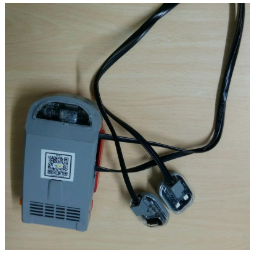
| RJ Cables |
• Standard network interface for telecom/data devices. • Enables connection between sensors/motors and motherboard. • Commonly uses RJ11 connectors for robot wiring. • Ensures smooth data and power transmission. |
General Coding Components used:
| Component | Description |
|---|---|
| List Picker |
• Displays a list of Bluetooth devices. • Acts like a button for device selection. • Customizable via the Properties panel. • Supports text, height, width, and color changes. |
| Label |
• Used to display static text. • Common for headings and notes. • Does not allow user interaction. • Style (font, color, size) is customizable. |
| Buttons |
• Triggers actions when tapped. • Detects user input (click/tap). • Fully customizable appearance. • Can be enabled or disabled. |
| Notifier |
• A non-visible alert/log tool. • Displays messages and alerts. • Helps debug apps via logs. • Improves user communication. |
| Bluetooth Client |
• Enables Bluetooth functionality. • Connects app to external devices. • Transfers data between app and robot. • Required for robot communication. |
Testing the app.
1.Start the bluetooth for the device and pair it with the qbrick( the qbrick number will be shown in the available devices).
2.First, go to the Build item of the menu bar and click on the App(provide QR code for apk).
3.Scan the Qr code with the MIT AI2 Companion app and download and install the app.
4.After installing the app, open it and click on the Connect button, it will take you to another black screen which will show the Qbrick version number, click on that and wait for a few seconds till your app is connected.
Project 1: Lyanna’s Light Avoider
Robot Components Index:
| Component | Description |
|---|---|
| LDR Sensor |
• Light-controlled variable resistor. • Resistance decreases in light, increases in dark. • High dark resistance in absence of light. • Useful for detecting light intensity. |
| DC Motors |
• Converts electrical to mechanical energy. • Range varies from 0 to 255. • Produces clockwise & anti-clockwise rotation. • Used in wheels, fans, pumps, and compressors. |
Coding Components Index:
| Component | Description |
|---|---|
| LDR Sensor |
• Represents the hardware LDR Sensor in the app. • Connected to robot via Bluetooth. • Retrieves real-time light data. • Uses block methods to fetch sensor values. |
| Motor |
• Used to program the hardware motor. • Set wheel rotation speed and direction. • Controls robot’s movement actions. • Integrated via Bluetooth control blocks. |
Assemble the project
Tasks Division:(Similar for making and breaking the model)
Divide the below tasks to each 4-kids group
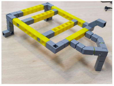
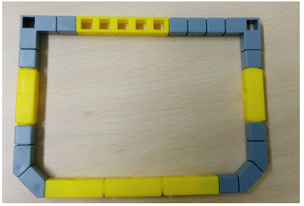
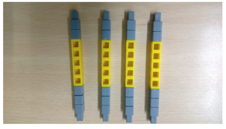
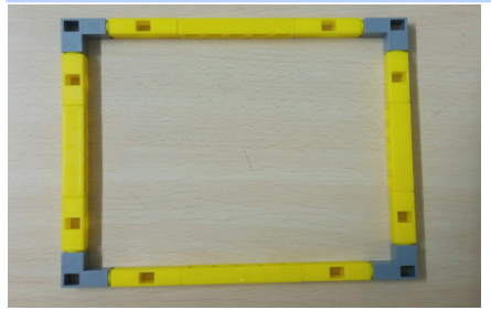
Task 1: Create the base of the light avoider using Qbits.
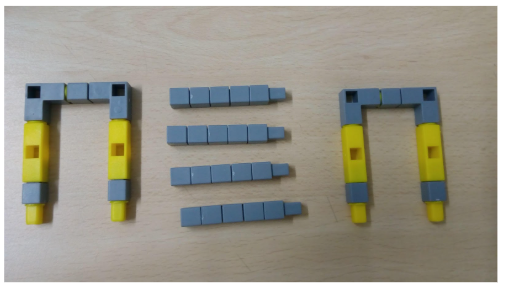
Task 2: Create the blocks that will be used to attach the castor wheel and the LDR sensor.
Task 3: Create the support for the QBrick and blocks for the wheels to be attached.
Task 4: Join the wheels to the DC motor and connect the left wheel to port M1 right wheel to port M2. to the Qbrick Connect the LDR sensor to port P1.
Steps to make the model:
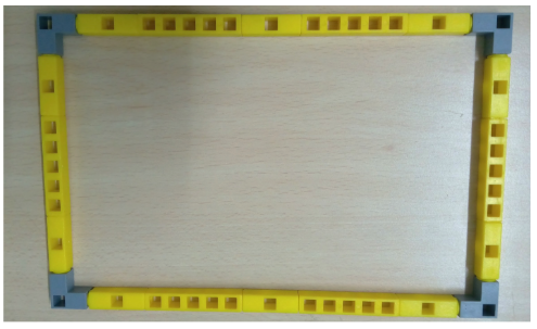
1.Make the base of the light avoider as shown in Task 1 .
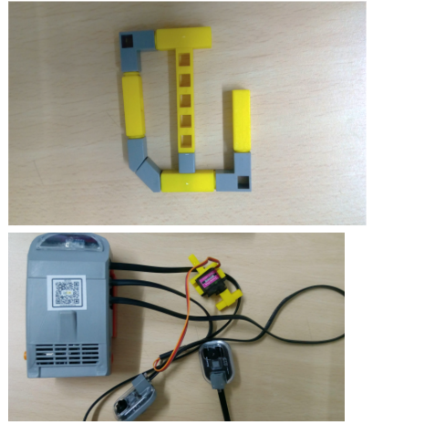
2. Connect the house shaped loop as shown in Task 2 to the front and attach the castor wheel to it.
3.Connect the support for the Qbrain as shown in Task 3 on the other side of the base.
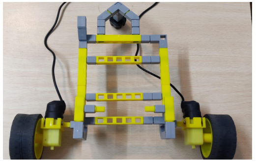
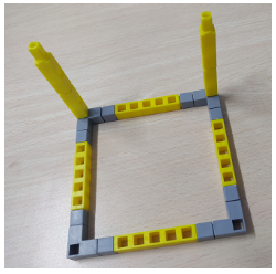
4.Now attach the wheels at the sides. Your model should be like the picture below.
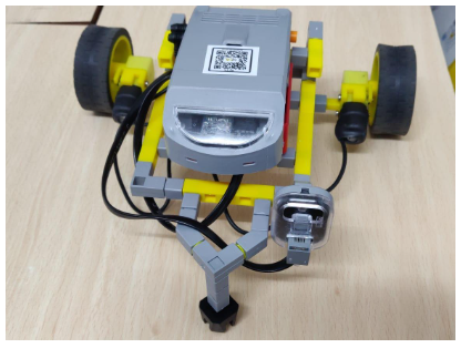
5.Attach the LDR sensor to the front and the motors to the Qbrick ports.Now you should have the below picture.
Task division:
4 students will share the same computer. Each student will code at least one set of code block.
Coding the Application
Designing the Layout
Steps to follow:
1.Drag and drop a ListPicker from theUser Interface and set the text in its properties to CONNECT. Rename the component from Listpicker1 to Connect.
2.Next drag and drop 4 labels from the user interface on to the screen and do the following:
- i) Label1:– Set the Text in the properties panel to “LDR Value” and rename the label to ldr_label
ii)Label2:– Set the Text in the properties panel to “0” and rename the label to ldr_val.
iii)Label3:– Set the Text in the properties panel to “Thumb value” and rename the label to thumb_labl
- iv) Label4:– Set the Text in the properties panel to “0” and rename the label to thumb_val.
v) Slider: Set the min value as 0 and the max value as 1024. Set the width to Fill parent.
3.Add the next components on to the screen:
- i) Notifier: Drag and drop this component from the User interface
ii)BluetoothClient:Drag and drop this component from the User interface.
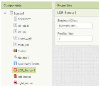
iii) LDR Sensor: Drag and drop LDR sensor component onto the screen. Next set the bluetooth Client and the port as well.(shown in below figure).
iv) Motor: Drag and drop 2 motors from the QtPi blocks onto the screen.Rename them as left_motor and right_motor. Next set the bluetooth client and the port number as shown in figure.
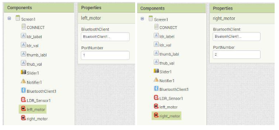
(Note : Port Number should be the port on which the sensors are connected .)
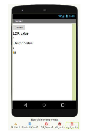
Your app screen layout will be like the below given picture
4.Now go to the Blocks panel to code the app.
5.Perform the below steps in order.
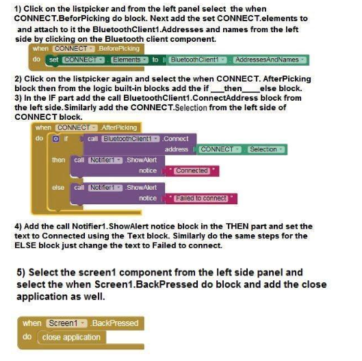
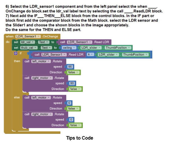
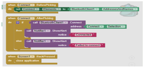
Note: Steps 2 , 3 and 4 are for connecting the app to the model via bluetooth and hence are common in every project. Do avoid doing it again and again for all projects do the following steps:
- i) In the right corner of the Blocks screen there is a bag, select the complete block and drag and drop it into the bag.
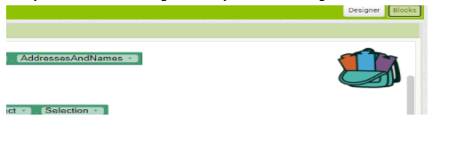
ii) Click on the bag and should see all the blocks of steps 2,3 and 4 in the bag. To use the blocks in the next project simply drag and drop the blocks from the bag
Project 2: Blake’s Basketball Counter
Robot Components Index:
| Component | Description |
|---|---|
| IR Sensor |
• Detects infrared (IR) radiation, invisible to the human eye. • Emits IR via Transmitter (TX) and detects reflection via Receiver (RX). • Senses object proximity based on reflected IR rays. • Used for object detection and obstacle avoidance. |
| RGB LED |
• Combines Red, Green, and Blue to create various colors. • Commonly used in displays, lighting, and visual indicators. • Acts as an actuator with a value range of 0 to 255 per color. • Suitable for decorative and informative lighting applications. |
Coding Components Index:
| Component | Description |
|---|---|
| IR Sensor |
|
| RGB LED |
|
Assemble the project
Tasks Division:(Similar for making and breaking the model) Divide the below tasks to each 4-kids group
Task 1: Create the base of the Basketball stand with two columns on 2 points of the square using Qbits.
Task 2: Create the second smaller base for balance along with the vertical column for the hoop of the Basketball stand using Qbits.
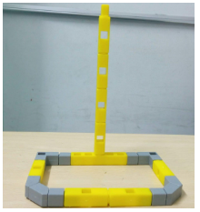
Task 3: Create the Basketball hoop.
Task 4:Take the QBrick and connect IR sensor(port 1) and RGB LED(port 3).
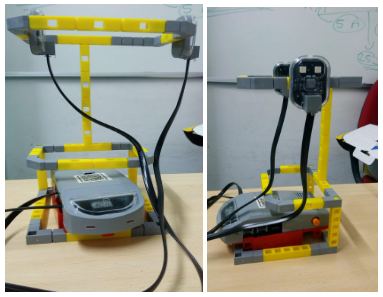
Steps to assemble the project:
- Make a base for the basketball hoop.Next add two vertical columns at two pints on the base (as shown in Task 1).
- Add the second smaller hoop with a vertical column (as shown in Task 2) and connect it with the 2 columns on the base.
Next connect the hoop you have made(as shown in Task 3) to the vertical column of the second smaller hoop. You will have the below figure put together at the end of this step:
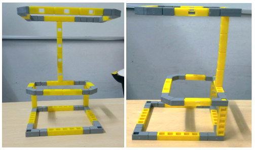
- Now connect the IR sensor to the left side inside the loop.
- Next connect the RGB Led to the outer side on the right side of the loop. Your end output will be like the figure below:
Task division:
4 students will share the same computer. Each student will code at least one set of code block.
Coding the Application
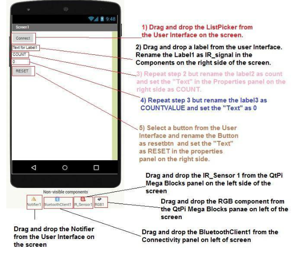
Designing the Layout
1.Follow the steps in the below given diagram to create the layout.
2.Do the following changes for the IR_Sensor1 and RGB1 component as shown in the below images:
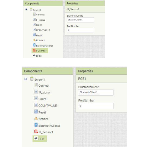
(Note : Port Number should be the port on which the sensors are connected on the Qbrick.)
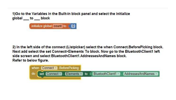
3.Now go to the Blocks panel to code the app.
4. Perform the below steps in order.
Project 3: Dora’s Door Alarm with Button Servo
Robot Components Index:
| Component | Description |
|---|---|
| IR Sensor |
|
| Buzzer |
|
| Servo Motor |
|
Coding Components Index:
| Component | Description |
|---|---|
| IR Sensor |
|
| Buzzer |
|
| Servo Motor |
|
Assemble the project
Tasks Division:(Similar for making and breaking the model)
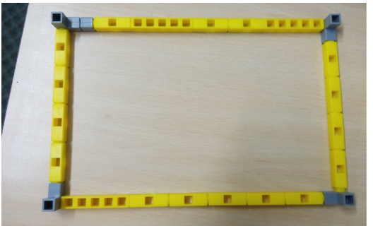
Task 1: Make the rectangle base of the house using QBits as shown below:
Task 2: Make 8 columns for 4 on all points of the rectangle base, 2 on width of the rectangle and 1 on each side on the length of the rectangle.
Fig1 : for all four corners of the base
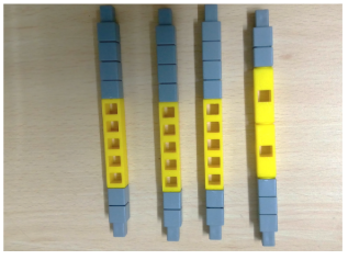
Fig 2 : 1 on each side of the rectangle and 2 on one side of the rectangle
Task 3: Make a roof for the house in a rectangular shape using QBits.
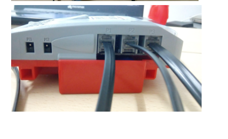
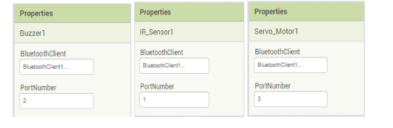
Task 4: Make a door for the house. Connect the IR Sensor to Port 1, Buzzer to Port 2 and Servo motor to Port 3 on the QBrick.
Steps to assemble the project:
1.First take the base of the house and connect all the 8 columns on the respective sides as mentioned in the above Task 2.
2.Next connect the roof of the house on top of all the 8 pillars.
3.Connect the Door to the motor and connect the motor to the last remaining side of the base of the house.
4.Add the buzzer to anyone of the pillars inside the house and the IR sensor to a pillar outside the house.
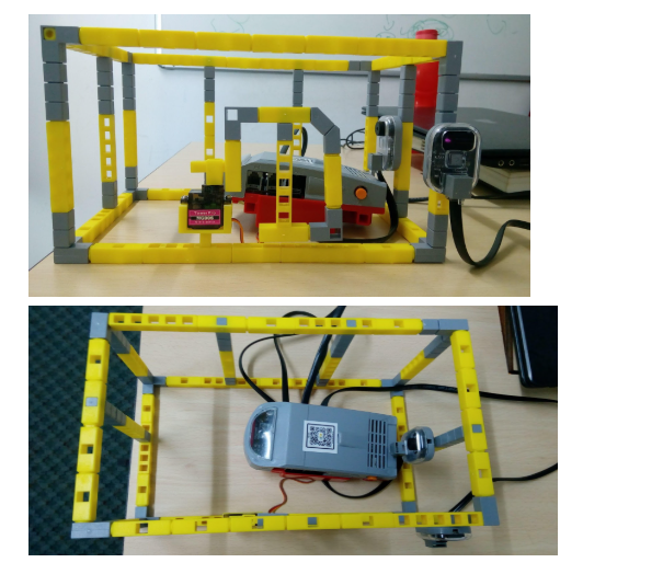
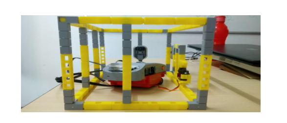
5.Your final model should be like the below picture:
Coding the Model
Designing the Layout
Steps for the app:
Follow the steps for the layout in the below diagram
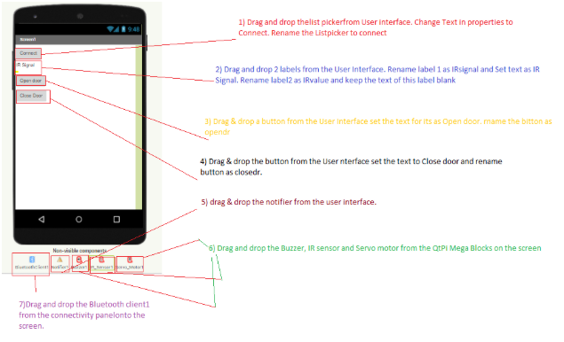
Set the properties of the invisible components as shown below.
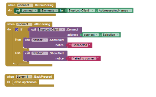
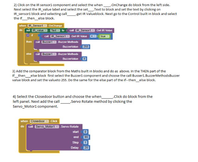
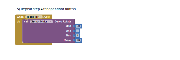
Now go to the Block panel of the screen and let’s write some script.
The bluetooth Connectivity part of blocks is the same as project 1.
Project 4: Principal Victor’s Voting Machine
Robot Components Index:
| Component | Description |
|---|---|
| RGB LED |
|
| Limit Switch |
|
Coding Components Index:
| Component | Description |
|---|---|
| RGB LED |
|
| Limit Switch |
|
Assembly of the Project
Tasks Division:(Similar for breaking the project)
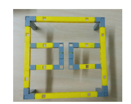
Task 1: Create a base for the Voting machine stand using Qbits.
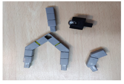
Task 2: Create 4 columns which will act as the legs for a base(Imagine a table). Also make 2 half rectangles as shown in image below on which the sensors will be attached.
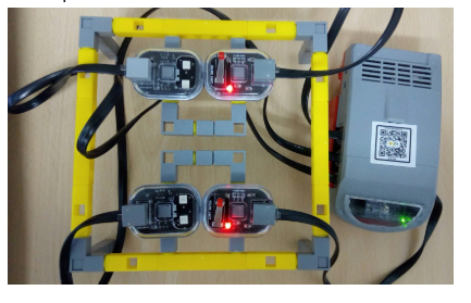
Task 3: Connect both the Limit switches to the QBrick on Port 1 and Port 4
Task 4: Connect both the RGB Led to the Qbrick on Port 3 and Port 2 .
Steps to assemble the Project
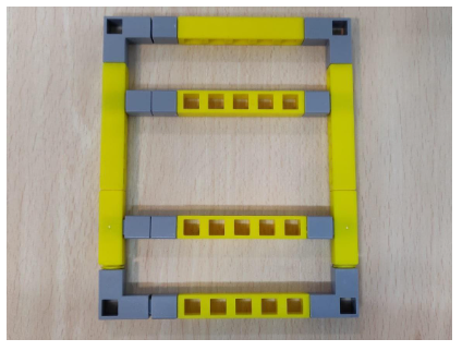
- First make the base(as shown in Task 1) using the Qbits.
- Next connect the 4 columns on all the 4 points of the base(should look like a table).
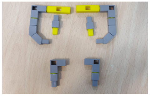
Next attach the half rectangles(in Task 2). Your model upon following these steps should look like the below image.
- Next attach 1 Limit switch and 1 RGB Led on each half rectangle and connect the Limit switches and RGB Led to the QBrick.See below image for complete model.
Coding the app for the Model
Designing the Layout
Steps to follow:
- Drag and drop a ListPicker from theUser Interface and set the text in its properties to CONNECT. Rename the component from Listpicker1 to Connect.
- Next drag and drop 4 labels from the user interface on to the screen and do the following:
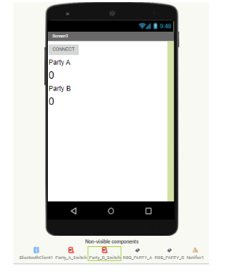
- i) Label1:– Set the Text in the properties panel to “Party A” and rename the label to partyALabel
ii)Label2:– Set the Text in the properties panel to “0” and rename the label to partyAvalue.
iii)Label3:– Set the Text in the properties panel to “Party B” and rename the label to partyBLabel
- iv) Label4:– Set the Text in the properties panel to “0” and rename the label to partyBvalue.
- Add the next components on to the screen:
- i) Notifier: Drag and drop this component from the User interface
ii)BluetoothClient:Drag and drop this component from the User interface.
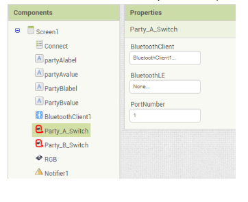
iii) Limit Switch: Drag and drop 2 Limit switch components onto the screen and rename each as Party_A_Switch and Party_B_Switch. Next set the bluetooth Client and the port as well.(shown in below figure).
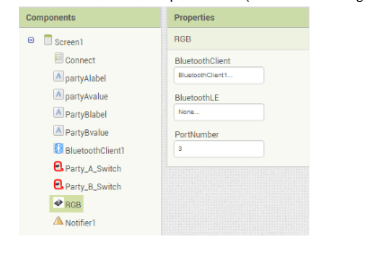
- iv) RGB Led: Drag and drop 1 RGB components onto the screen and rename each as RGB_PARTY_A and RGB_PARTY_B. Next set the bluetooth Client and the port as well.(shown in below figure).
Below should be the layout of your application.
7.Now go to the Blocks panel and let’s script.
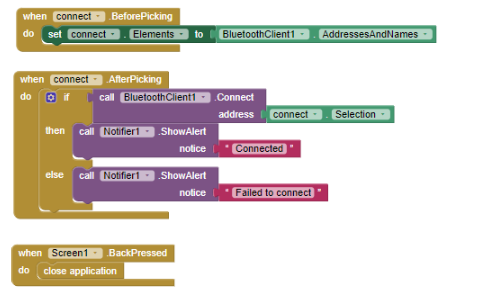
8.Do the bluetooth connectivity same as project 1
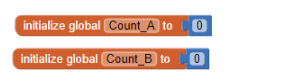
9 From the variables builtin block drag the initialize global ______ to ____ block on the screen.and set the value using the simple text block from the Math built in block.
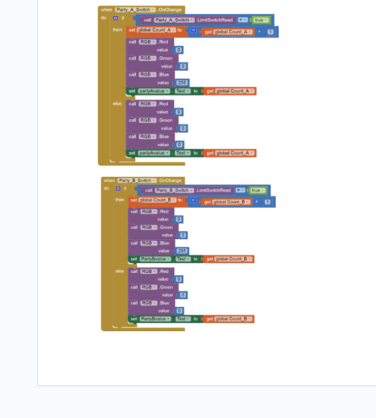
10. Next click on Party_A_Switch and from the left side chose the when Party_A_Switch.OnChange do ____ block .Next add the If ___then___else block from the control built in block .
11. In the If part add the comparator block from Math and choose the call partyAswitch____.LimitswitchRead as one operand and from the logic built in drag true block and set it as second operand.
12.In the then part first set the new value of count_A variable on each switch click by get count_A and add 1 to it.
13.Next use the call_____.greenValue, call____ blue value and call___redvalue and set the values to 0,255 and 0 resp. This will let the RGB Led emit blue light when the switch is on.
14.Next set the value of the PartyAvalue label by clicking on it and selecting the set____.text property from the left.Your final code for Part A Switch should be as the below figure.
15.Repeat step 12 to code for Party switch B. Your code should be as below.